A few words before we start
There are few things I would like to mention before we dig into the building process.
First of all, it is very important that you go through the whole documentation before you start to do anything. Give it a read at least one time, so you get comfortable with the process. Also, I’m not going to list the hardware tools we bought and used, so when you read it for the first time, you should get a good understanding of what tools you will need to get/have.
Second of all, because we built the computer around 3 months ago, there might be a black spot in this documentation where some specific information is missing. I’m not a bookwriter and the documentation will be full of text, so it’s very easy to make a mistake. In this case, please Contact me to let me know about this. I will update the tutorial as soon as possible.
This tutorial is also not the only way how to build the PC and you do not specifically have to follow every single step the way I do it. Feel free to take your own path, but think before you do.
Keep yourself organized. Split your room on sections – one for boxes, one for tools, one for screws and so one. You will save a lot of time if you do not have to spend 30 mins a day just looking for lost stuff. Also, clean up after every day of work so you keep your components clean and so your screws don’t get lost in the mess.
Lastly, manual work produces a lot of mess and noise. As I was a student back when we were building, we did it in my apartment and of course we managed to scratch the floor a little and also make a few scratches on the wall. Use a workshop if possible, if not, rent one. If you do not have any other choice but to do it inside of your home, protect the floor and the walls against damage.
Get the plywood
Plywood is suitable for this project because even though it’s heavier, it is very sturdy and you can be sure that it will hold the PC together. There are some types that are fire- and water-proof, but they are twice as expensive. We got the one that is water-proof, to protect it against wet Danish air. You will need two of them:
- 1pc 850x750x25mm for the main board
- 2pcs 150x150x25mm for 4 triangular spacers between the wall and the main board, one for each corner of it
Get the computer components
At this point, I already assume that you have your components chosen and on their way. As soon as they deliver, unpack them and move your boxes and receipts to one place so you can easily find them in case something breaks and you need to return it.


Get acrylic plates
The whole point of acrylic is to give components under-light. It’s not hard to find them on the internet and they are not as expensive as they used to be. Nevertheless, the supplier must be able to profile their edges. We couldn’t find any supplier on the internet who could do this (Denmark and UK) so we contacted one of the local workshops. The photo below describes our request.
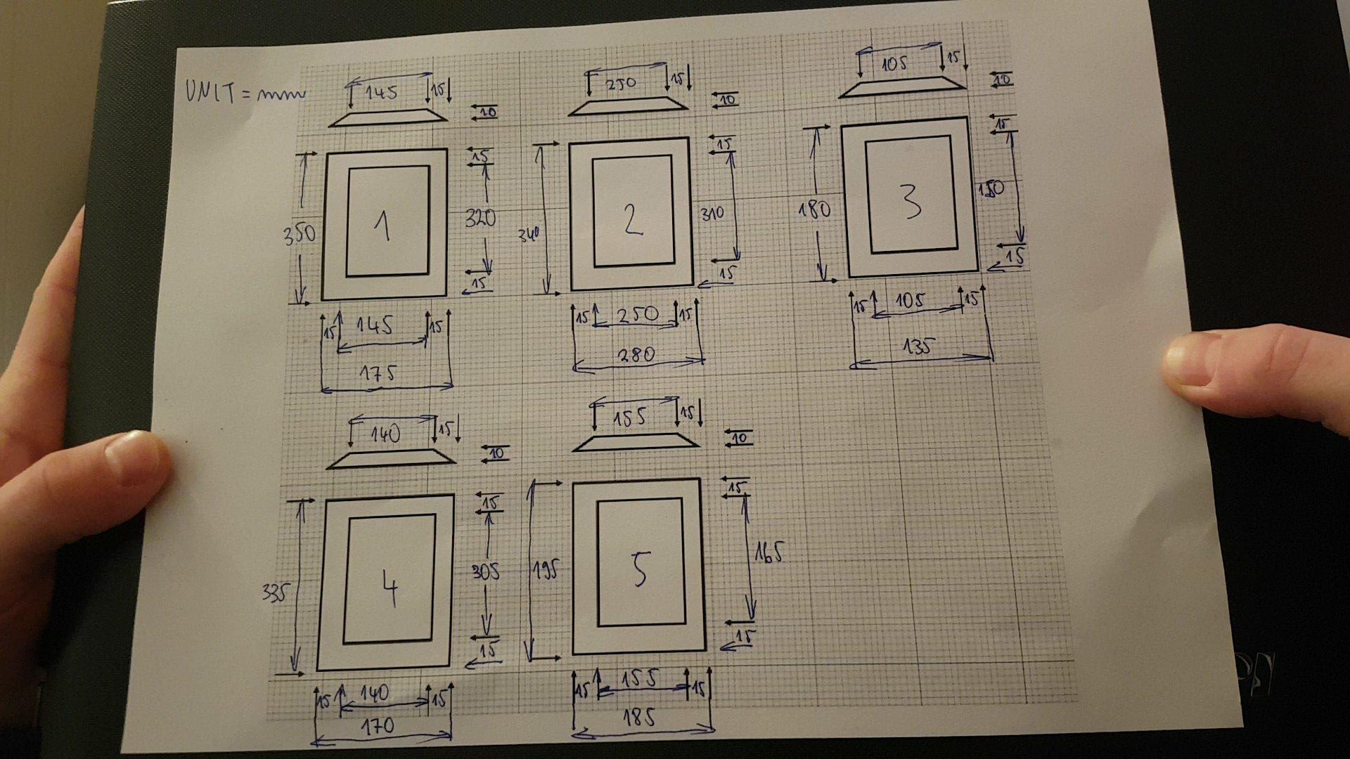
You can see that each rectangle represents an acrylic plate, with the component inside of it. The 15mm margin is left for edge profiling. We ended up using 10mm margins instead (I don’t have a photo of the second request), because that was the value of a 45° angle, which we wanted.
What you need to do is to measure your components (allow extra 2-3mm to each side) and have your acrylics done based on your sizes. The acrylic plates should be between 10mm and 15mm to avoid having either non-visible LEDs, or too many underlight, but it’s of course up to you if that’s something youre aiming for.
Draw components and cable holes on the board
Here’s where things get real. From now on, you have to be extra careful just about everything you do. You gotta bring your design to real life by drawing outlines of components on the main board. This will help you with drilling holes for LED lights, holes for mouting acrylic and so one. The outlines must have rectangular shape, as your acrylics will also be rectangulars.
Allow extra 3-5mm on each side of the component. This is my personal advice; we did it as well and it turned out to be the best thing we could have done. It can for example happen that your drilling bit will break in acrylic and get stuck there, and you will need another one right next to it to perserve your design – you will find these extra millimeters very handy. Also, you do not want to have the components look like they are bigger than acrylics, it wouldn’t be esthetically pleasant.


You also have to measure the width of your cables and draw holes for these. Again, allow a few extra millimeters, so it doesn’t happen that f.e. the riser’s connector won’t get through the whole. Be careful though, making the holes too big will not look nice at all. Keep the number of holes at minimum (less holes = better outlook) by merging the cables from different components into one holes.
HDD Seagate cover and GPU riser cable
We ordered two riser cables because we wanted to have them from Li-Heat and we needed 60cm in length in total. Li-Heat is one of the two best-quality producers of riser cables in the world, alongside with 3M. 3M only offers their cables coated with silver material, which wouldn’t look good on our rig. Li-Heat only offers these cables in 20-50cm in length, but you can connect one to another without worrying about performance.
The seagate cover was made by me and it is up to you if you want to follow. In case you’d like to make one, you need to measure the top side of it and cut out a piece of plastic with these dimensions. Then, cover it with the same adhesive foil that you will later use for the top of the main board – allow a few centimeters on each side, so you cover the sides of your HDD/SSD as well – this will hold the cover on its place. After that’s done, place the plastic on the drive, take a small knife and cut out anything you want. Be careful not to scratch the plastic.


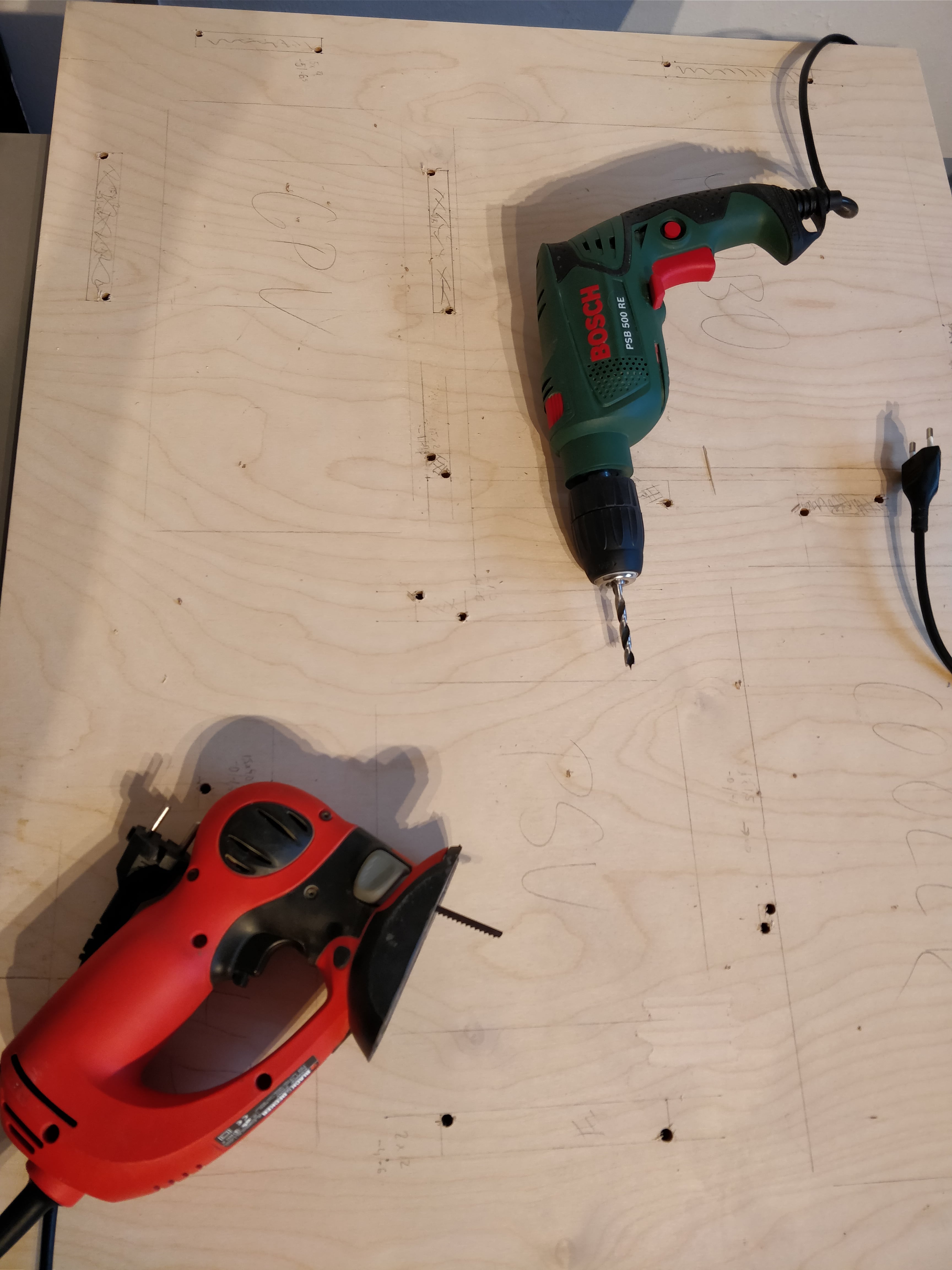
Drill the cable holes
Use a drilling machine to make two holes for each cable hole (follow the images). After you have these, use a jigsaw with a small blade – one that fits into the holes. Make a rectangular hole for each cable hole. Don’t worry – the rectangles will look like s**t at the beginning.
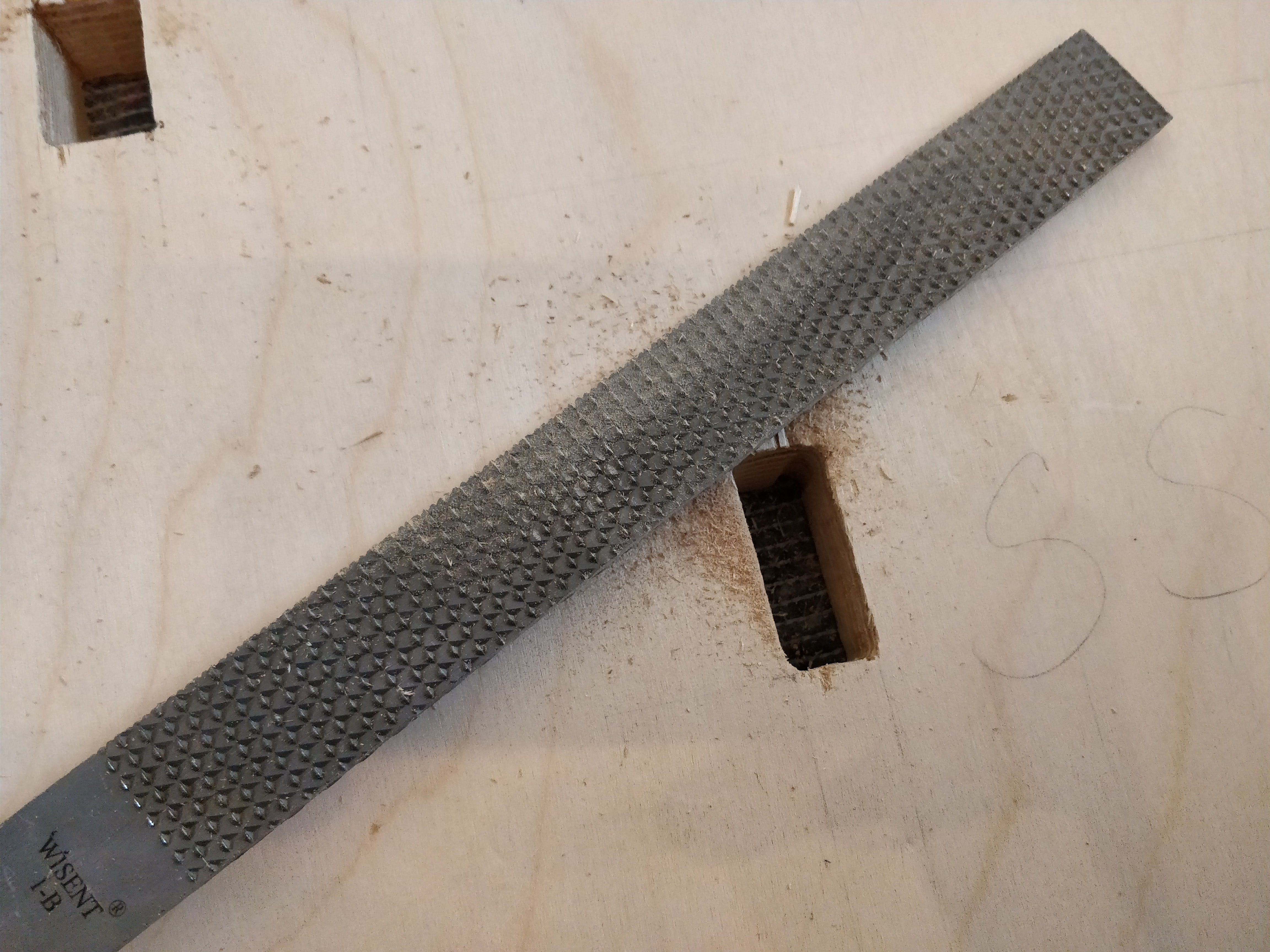
You should have some files and rasps at home, if you don’t, get some. You will need them for the final touch on the cable holes. Work them until they look as you wish – we were okay with curved rectangles – they will be covered with adhesive foil later on anyway. It’s just about making them the same size from the top and bottom side of the main board, and a little bit better looking.
Filing/rasping will take you some time and takes a lot of energy. So does the next step. Finish and have a beer before going further 🙂
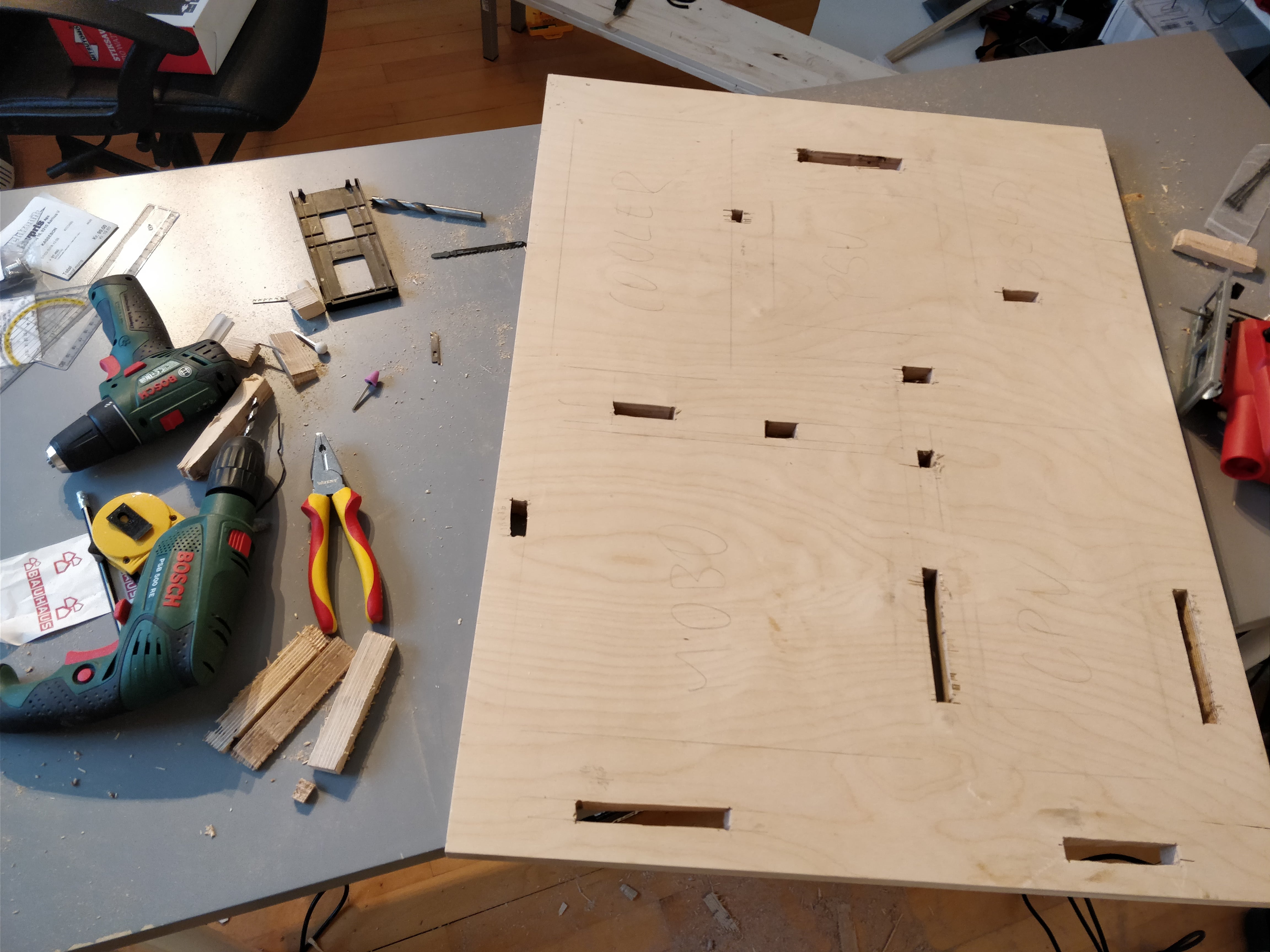
Chiseling slots for LED strips
This part is very difficult and the only way I can help you is that I will point you to the right direction. I saw some tutorials on the internet where people put the LED strips on the rig differently, and this is definitely the more difficult solution, but having LEDs right under acrylic makes it shine more.
The idea is that each acrylic should have notches or a small “valley” on the bottom side. Light breaks when it reaches a surface that is not flat. We will use physics in our advantage, but I will describe this later on. For now, all you have to know, is that you have to make the slot exactly on the place where the “valley” will be when you place the acrylic on the main board. It’s a bit difficult to do – for now, let’s just make the slots.
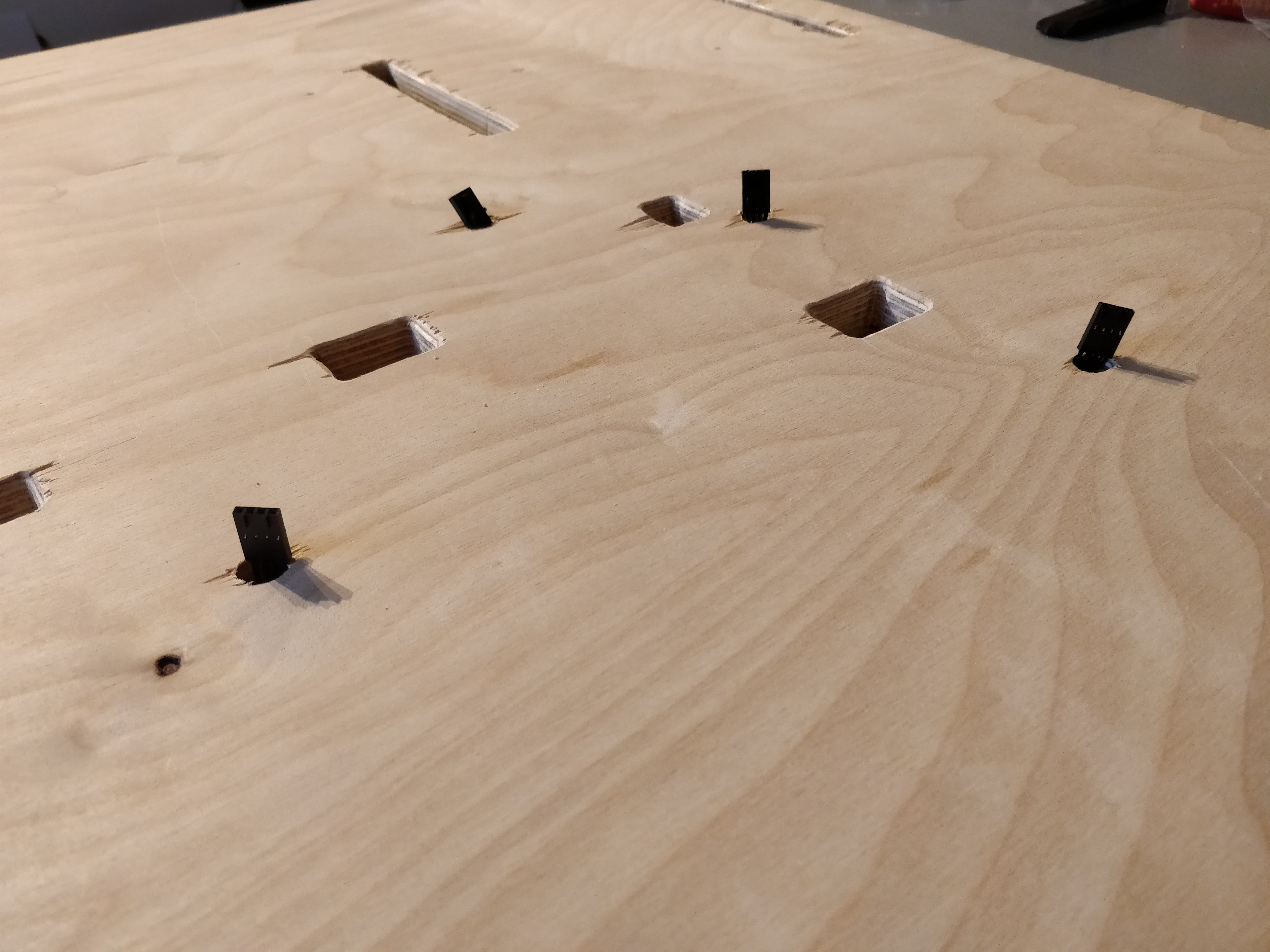
Each LED strip has it’s body and two connectors on each side. These connectors will be connected into lightning nodes on the back side of the main board, which means we need to drag them through the main board on both places. You will not always use both connectors, but it’s a good idea to do this with both connectors for each LED strip for extra flexibility.
So the first thing to do here is to measure the length of LED strips. If you follow our design, some slots will be shorter than the strips, which is perfectly fine, and some will be a perfect fit, but you do not have to worry about slot being too long for the strip.
The second step is to draw an outline of the LED strips after you place them on the main board. Avoid having a light on the LED strip too close to the component outline.
The third step is the chiseling itself. Make slots just as deep as the height of a LED strip that you use, or a bit deeper.
After you’re done with these steps, try to place the strips into the slots to see if they fit. Do not take off the adhesive paper cover yet.
Chiseling will leave your surface “scared”, so I suggest you buy a wood filler and use it to make the surface as flat as possible. This way thhe adhesive foil that will cover the main board will fit perfectly on any place of the surface.
Sand the main board surface
As easy as it sounds. Just take a sanding paper/sanding machine and sand the whole surface of the main board.
Marking light spots/”valley” on the acrylic
This is a huge pain in the ass and it was hard to figure out. As I said before, light breaks when it reaches uneven surface. If you place your flat acrylic on a LED strip, it will only shine on the top side of the acrylic, just where the light is. It won’t reach sides of the acrylic and that’s basically what we want. The top of acrylic will be covered with adhesive foil too – the only shining part will be the profiled edges. So we need to break the LED strip’s light as much as possible.
The better way is to make a valley in V-shape on the bottom side of the acrylic. Length of the valley should match the length between the first and last lightning spot on the LED strip that will be visible on the top side of the main board. I’m not exactly sure how you can achieve this – acrylic melts when it comes in contact with high temperatures and any heavy machinery could break or melt it. If you want to go for this better solution, I’m sad to say I cannot help you and you have to find an answer on the internet.
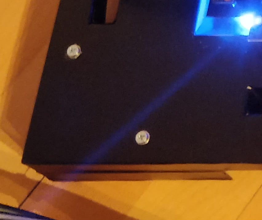
There is an easier way that is (almost) just as effective. I figured that practically any harsh sufrace can break light and even making 5mm (half through the acrylic) holes into the acrylic with a drilling machine could do the job. While I was buying acrylic from the local workshop, I asked if they do not have pieces that they no longer need, so I can test on those, and they gave me a few pieces. I took these and did some lightning testing and surprisingly it worked. Below, you can see the acrylic plate with two holes, fitted onto place on the second photo.


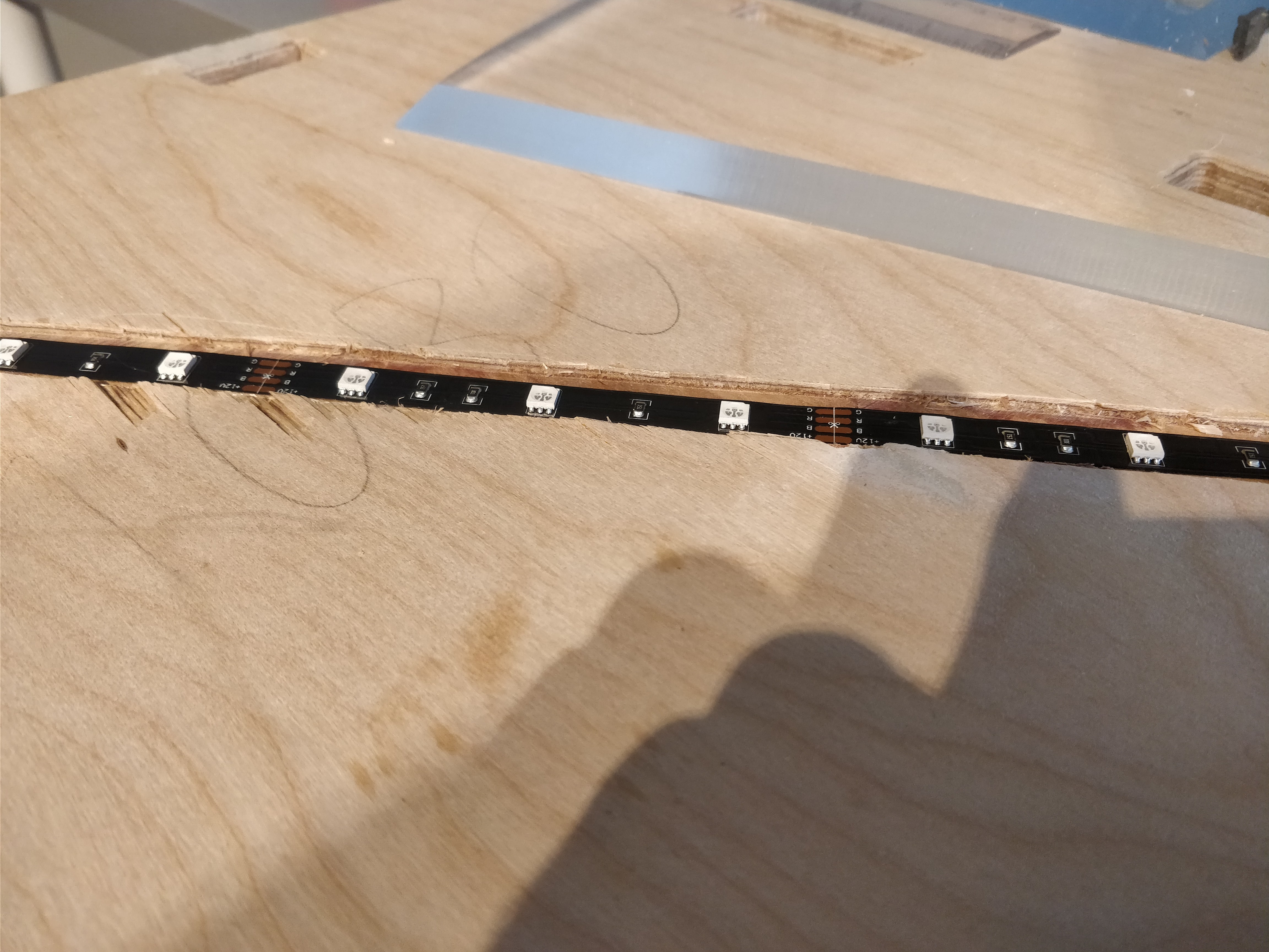
For this step, you need to have your LED strips on place and not move them from now on at all.What you need to do is to decide where your Commander Pro, Lightning Node Pro and RGB Fan Led Hub will be placed on the back-side of the main board. Then, you have to plug all strips together and try to connect them – 6 to Node Pro and 2 to Commander Pro (in series, using one Commander Pro connector). You will have a bunch of cables on the backside – they cannot block the cable holes of the main board and you also have to be prepared for some obstacles along their way, so having a cable between one of the nodes and a LED strip connector stretched out to maximum is not an option – again, allow a few extra centimeters, so the cable is loose.
It will probably take you some time until you find the best solution, but after you’re done, you can take off the adhesive covers of the strips and place them in the slots on the main board. From now on, these lights are sturdy and if you take them down again, you will also have to glue them back.
By now you already have your component outlines marked on main board. You now have to mark the acrylic outlines too. Simply draw another rectangle based on the size you requested when buying acrylic. Place acrylic on these outlines and mark the places where lightning spots of LED strips are. After you’re done, take the acrylic off, turn it upside down (bottom part on the top). You should now see these marks. Make holes where the marks are – try to be as precise as possible. Holes should be roughly 5mm deep.
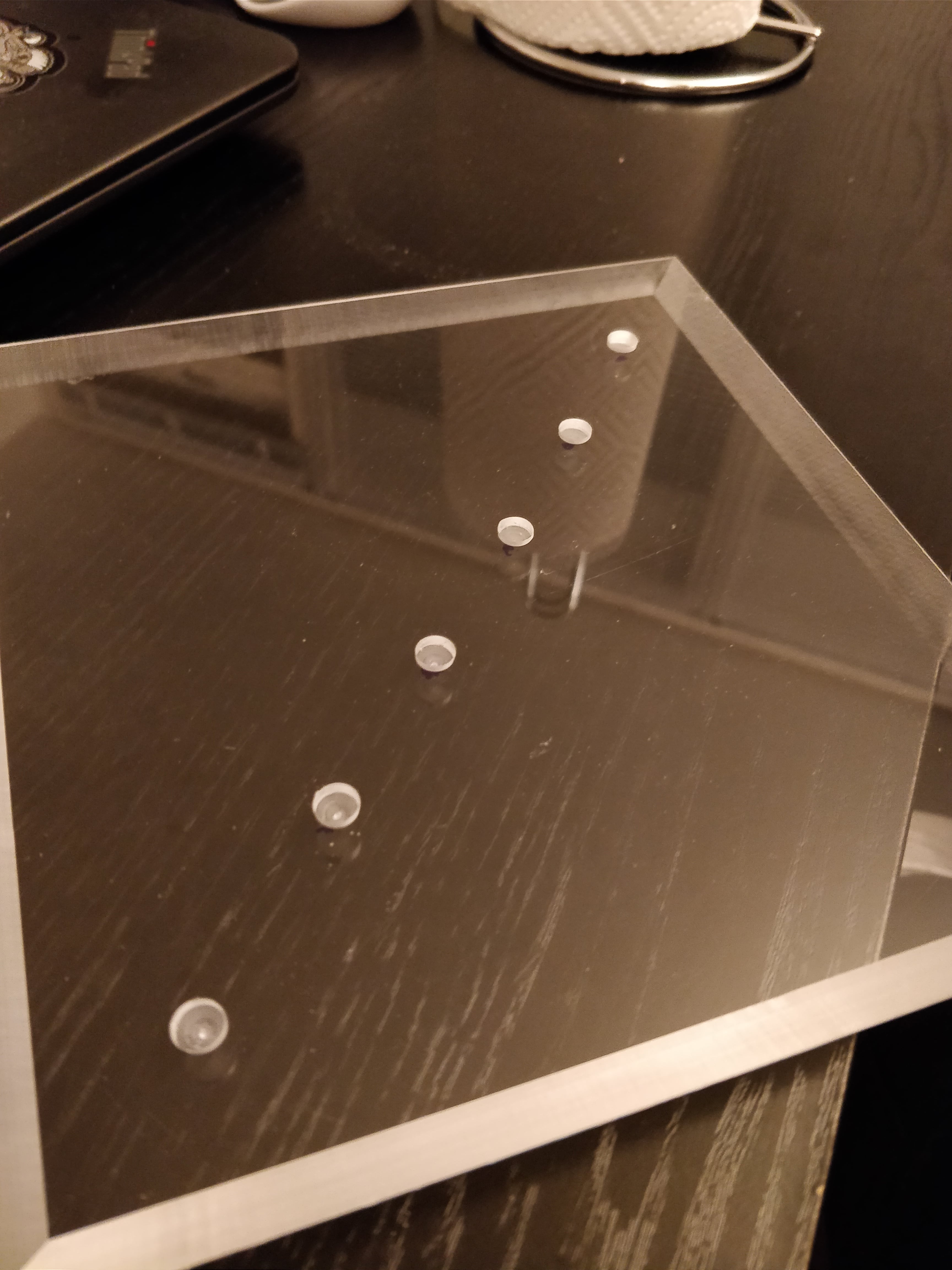
The picture shows the bottom part of one of the acrylics. Holes are actually smaller, we ended up making them bigger, as we did not know how big to go while preparing the first plate.
Mount acrylics on the main board
It’s time to make mounting holes for acrylics. You won’t actually leave the acrylics on for now, but you have to have the holes ready, as the next step will involve covering the main board with adhesive foil. This will make the acrylic outlines invisible – holes will help you with positioning acrylics on the main board from now on.
It is up to you where you make the holes. Start with acrylic plates – decide where the mouting holes will be and mark them. Choose what screw you will use. The screws will be fixed with hex nuts from the bottom side of the rig. They should be between 30mm and 40mm long to allow space for hex nuts while not being longer than distance from the wall to top of the main board. We used screws that were 10mm wide on head and 5mm wide on the body.
Use three screws for heavier components, such as motherboard, CPU radiator and GPU, and two screws for the rest of the components. Drill holes into acrylics (drilling bit according to what screw size you chose) and then place them on their place on the main board. Use a pencil or a marker to mark the hole spots on the main board. Drill holes of the same size, or +1mm for easier screwing, to the main board.
Take the acrylics back in hands and drill a tiny hole of the screw head size (for us, it was 10mm) on the top side of the holes. Something like 2mm should be sufficient – we do it just so the screw heads do not stand off so much when screwed in.
Cover the main board with adhesive foil
Now that you know where the acrylics will go, based on the holes you drilled in the step above, you can place your adhesive foil on the board. You do not have to cover the back side, but do cover sides too – they will be visible on the wall as well.
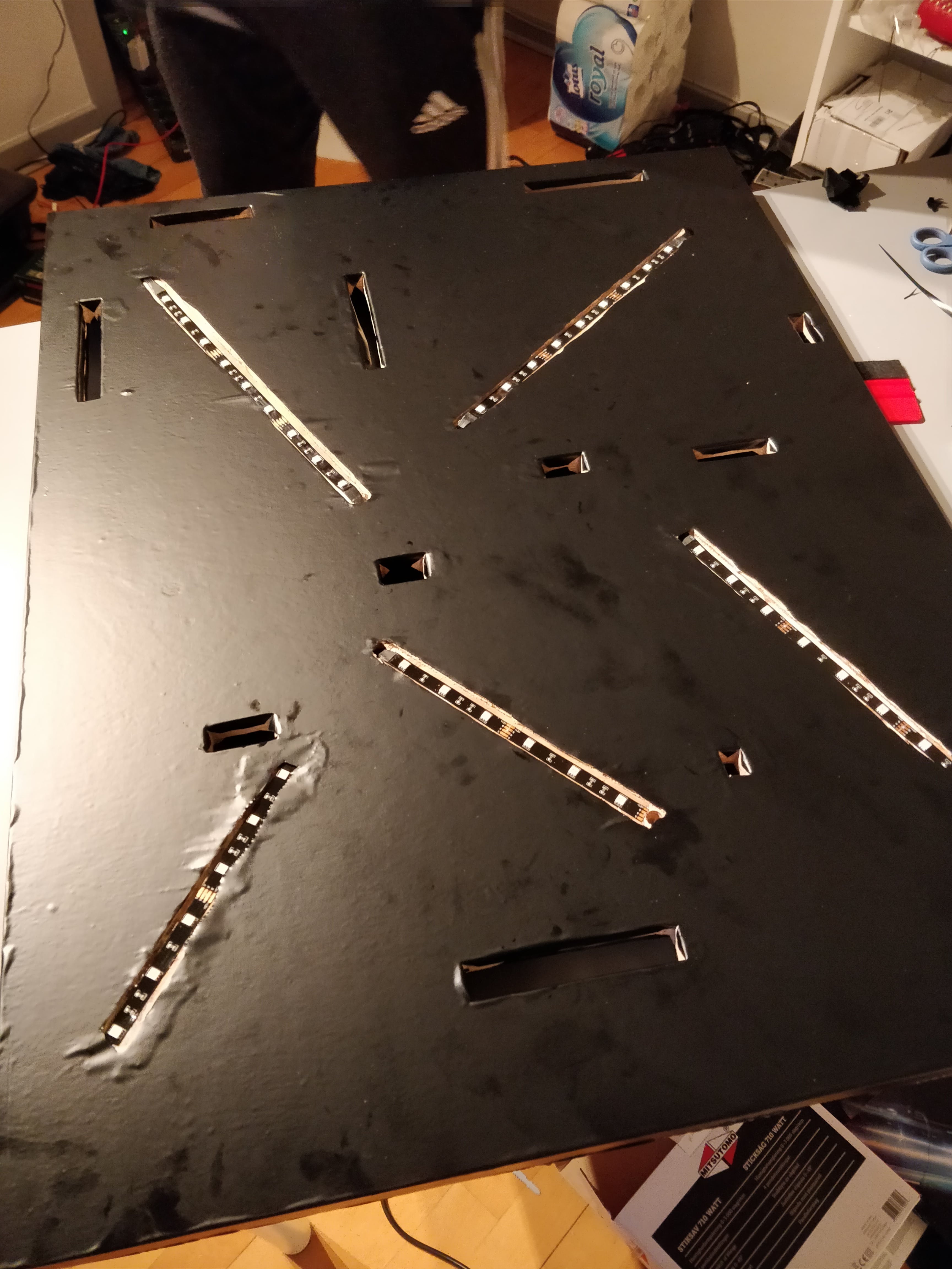
Cut through the cable holes. Cover the insides of cable holes as well, so they get the same look as the rest of the computer. Then, cut out the slots for LED strips – you should be able to recognize them by hand, but be careful not to cut through the strip itself.
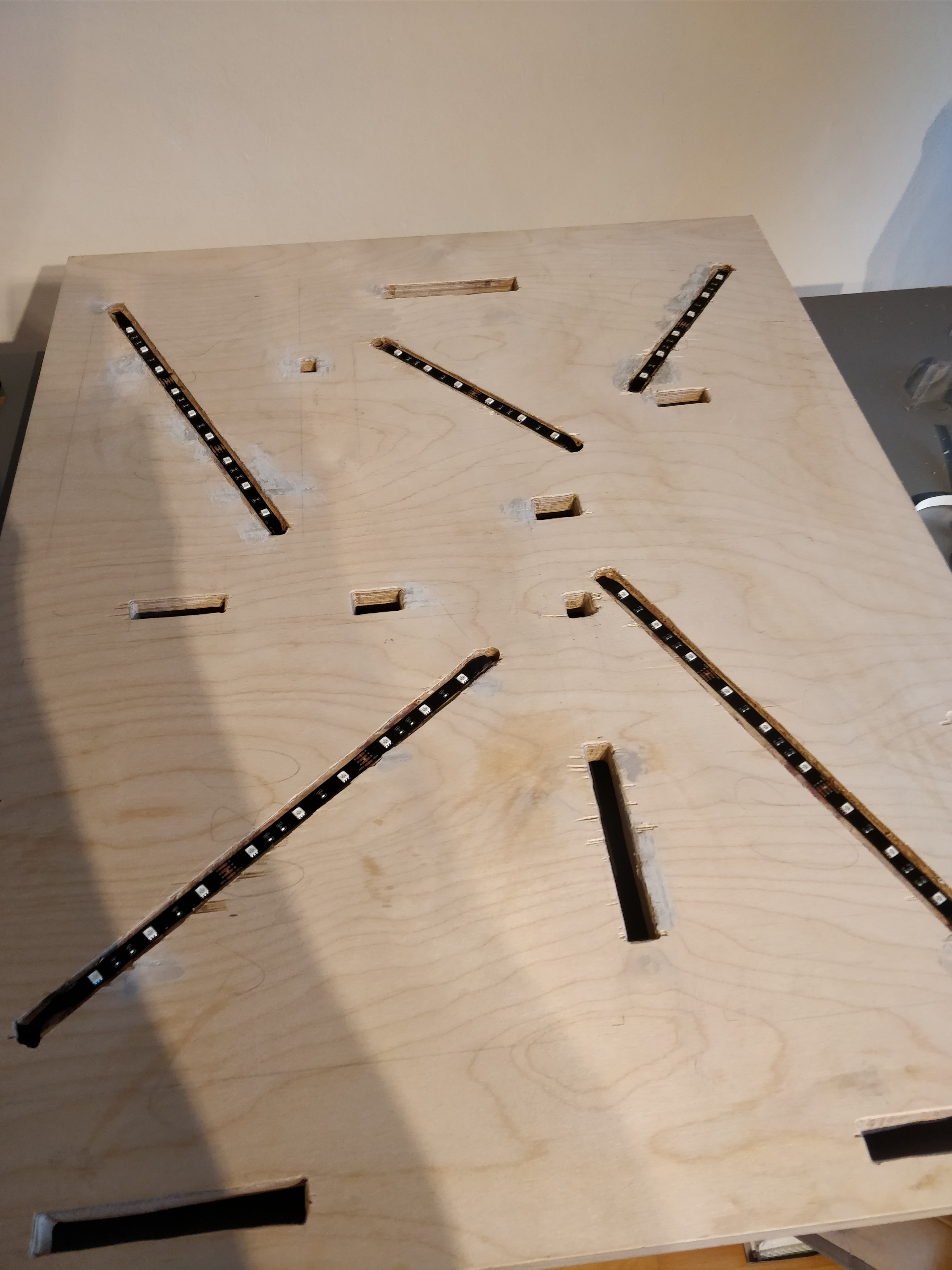
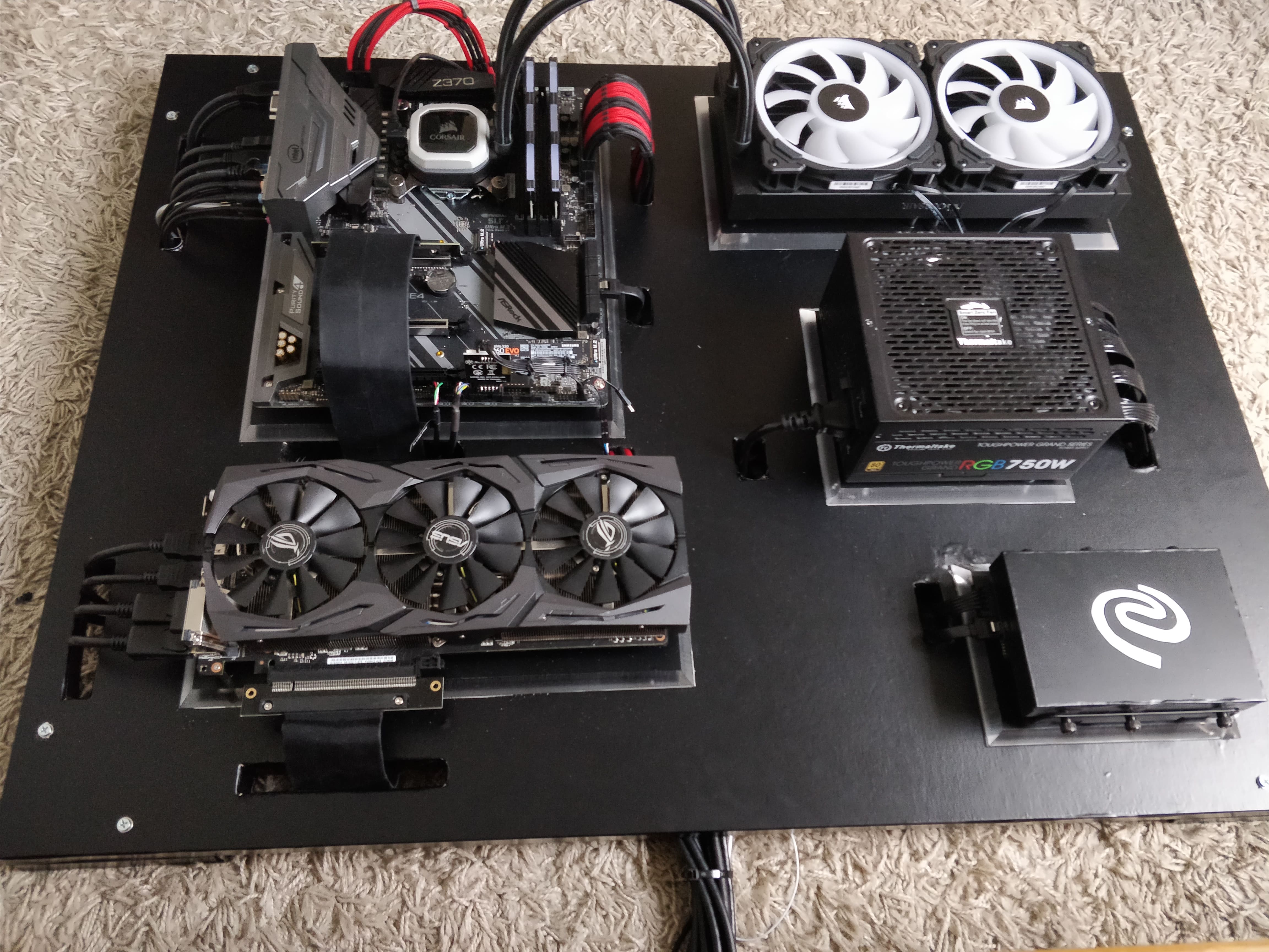
The picture below shows what your rig should look like by now. We didn’t manage to place the foil on the board nicely, so we bought another one and tried again; unfortunately I do not have a picture of the second try.
Mount acrylics to the main board
There are two types of mouting components onto the acrylic plates – from the top, and from the bottom. For some components, you need to put screws into acrylic from the top side. These components are motherboard, PSU and HDD/SSD and you do it from the top because you put screws through the component from the top side.
On the other hand, some components are mounted using screws from the bottom side. GPU has holes on its back side, which are used to hold the backplate and cooling on it. You don’t usually use these, but the way we mount it is different than what you do when you have a standard PC case (I will get to this in-depth later). CPU radiator is also mounted by putting screws in from the bottom side in order to have fans on the top.
For now, you should only mount the first three acrylics – leave the radiator acrylic and GPU acrylic for later.
Cover acrylics with adhesive foil
Not much to say here – simply place the foil on the top part of all acrylic plates – leave out the edges.
Mount CPU and cooler unit base on motherboard
Now is the time to mount the processor and the cooling unit on the motherboard. If you want to have one of the four Commander Pro temperature meters under your motherboard as we do, glue/tape it to the top of the acrylic plastic anywhere you want (optionally next to a cable hole).
You shouldn’t mount the CPU cooler unit on the processor yet. They come with a mounting bracket – this is what you want to mount for now. Leave the cooling unit and the radiator for later.
Mount motherboard onto acrylic
Take the piece of acrylic that belongs to the motherboard. Put motherboard on it and try to center it, so there is the same amount of space around every side. Then, take some sharp tool and make a little hole in the foil where screw holes on the motherboard are – there should be 9 of them for ATX motherboards.
ATX motherboards use M2.5 standoffs, usually of some small size. We got ourselves a 20mm long version (8mm screw, 12mm standoff). M2.5 standoffs are 2.5mm wide on the screwing part. Make a hole in the acrylic with a 2.5mm drill in each place you marked – it should be 8mm deep, so almost all the way down. Again, be careful, it is extremely easy to break this tiny bit in case it gets stuck, and if that happens, you’re truly screwed. We broke one and ended up using just 8 screws to fit the motherboard in place.
After you have the holes ready, screw in the standoffs – be careful here too, it is just as easy to break a 2.5mm bit, as it is to break a 2.5mm standoff.
Finally, mount the motherboard on the standoffs. You can leave the CPU radiator right next to it on the main board so the water pipes do not damage.
- Links
- Standoffs – https://elektronik-lavpris.dk/p136596/da5m25x20-afstandsbolt-l20mm-m25-udv-indv-gevind/
Mount PSU onto acrylic
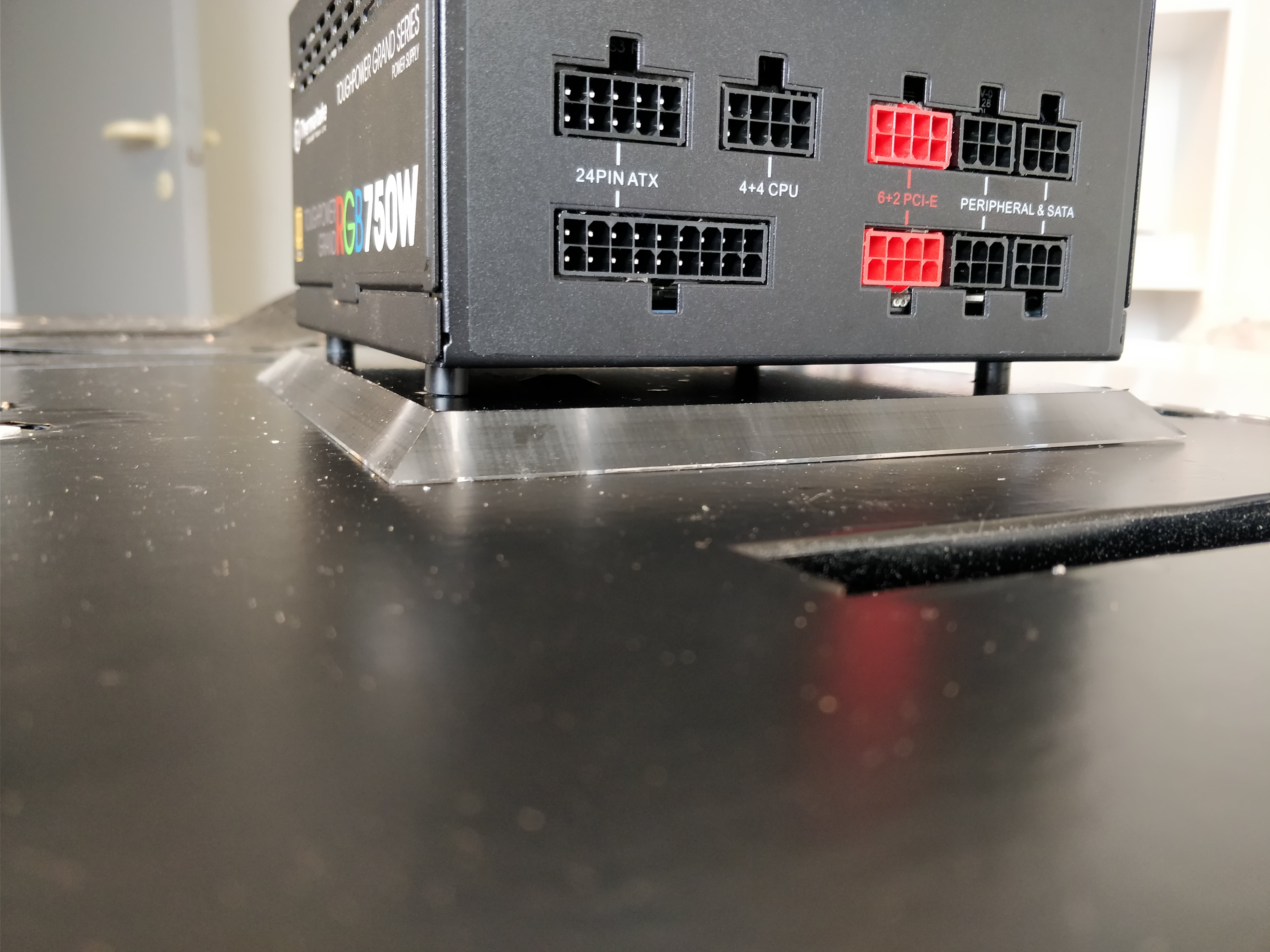
Unfortunately, I do not have any pictures of the PSU from inside, but if you place it in front of yourself top up, you should see some screws from the left, top and right side of it. You have to take all of them down – while you do this, you void the warranty by removing the protective sticker.
After you take the top cover down, you will see the inside of the PSU. Notice 4 screws on the bottom in each corner – you have to take these screws out and examine their size. I can’t tell you precisely what the screws were for our Thermaltake, but I’m absolutely sure that it was either M2.5 screw or M3 screw.
Buy some in the shop, or on the internet. We ordered ones with 20mm length. There is a slight standoff between the screw head and the PSU floor – it was something like 2mm or so, which means that our screws went in 8mm deep (don’t do math, continue).
Take the original screws out and do the same as with motherboard – center it and mark where screw holes are. Then, drill holes into the acrylic – if the PSU works with M3, you will need a 3mm bit; if it works with M2.5, you need 2.5mm bit, and so one… Go 8mm deep; you can also go hrough the whole acrylic if you want, no worries.
Because PSU tends to get hot, it’s a good idea to place it onto standoffs to allow air circulation between the acrylic and the PSU. You need four 10mm spacers for this. It is also very important that you isolate the screw head from the body, just in case. The PSU electronic board has circles marked around the screw holes. These will give you an idea of how big a screw head can be. Our screws were smaller, but it is a good idea to isolate anyway – just in case. So each screw should be placed on top of a nylon washer – these usually come with motherboard screw kits.
Start by placing the PSU on four spacers. Put a washer on each screw. Then, use some tool (tweezers or so) to move each spacer around while you put the screw through the PSU to find the sweet spot – don’t put the screws in acrylic yet. Repeat this process with each of the spacer and the screw. After you’re done, start screwing them in.
Then, check if the PSU holds sturdy. Lastly, mount the PSU cover back on the top of it.
- Links:
- Spacers (10mm) – https://elektronik-lavpris.dk/p86879/kdr10-ps-spacer-sleeves-36-10mm/Nylon washers – https://www.aliexpress.com/item/100PCS-Red-Motherboard-Screw-Insulating-Fiber-Washers/32826569766.html
Mount HDD/SSHD onto acrylic
We got ourselves an SSHD from Seagate, which has exactly the same proportions as a standard HDD. These harddrives do not have mounting holes from the top or bottom side, only from left and right side, as they are usually mounted horizontally into the PC case rack. We need something to adjust the mounting possibilities.
The Phanteks 3.5” bracket is a great thing. It has plenty of holes for screws, although you only need two to mount the HDD and keep it there forever. The best idea is to use 4 of them, for extra safety; we ended up using three of them in a V shape.
Again, center the bracket on the acrylic, mark the holes and drill them. It is absolutely up to you what screws you use here – go with whatever you’re comfortable with. You again want to use spacers here (HDDs get hotter when under load) to allow air circulation. 10mm will be sufficient here as well and you need as many as the number of screws you decided to put in. What you should be aware of is that if you buy a screw too thick, you might not be able to pull it through the spacer.
After you’re done, mount the bracket on the acrylic and then mount the SSHD to the bracket. Voila!
- Links:
Mount CPU radiator onto acrylic
This part is trickier and it is the first out of two components that are mounted from the bottom. Take the radiator into your hands and look at the bottom – you will see a number of screw holes. These radiators are usually mounted on the top of the PC case from inside (fans facing bottom), that is why the screw holes are not on top of the radiator. Do you see why this is getting more complicated?
In order to mount the radiator, you have to make holes into acrylic from its bottom side. This is why I told you not to mount the acrylics for the radiator and the GPU just yet – we will need to do some extra work with them.
Take your radiator and turn it around (fans facing the table). Then, put the acrylic on it – the top side of acrylic should face the bottom side of the radiator. You can now see where the holes are. Try to be as precise as possible now, because you will have to mark the acrylic plate on places where screw holes are.
Corsair H115i Pro comes with a few very long screwes, so you don’t have to worry about those, but you should choose a drilling bit that complies with the size of them. After choosing, drill holes where you marked them. Then, take a bit that is a little bigger than the screw head and widen the holes 2-3mm in depth, so the screw head can disappear in the hole, otherwise the screw heads will create space between the acrylic and the main board.
You will again need some spacers and there is no way to tell you the exact amount of them here. Just to be sure, take 12 of them. It all depends on how deep you go when you widen the screw holes. Put a Corsair screw through each of your holes and then put spacers on it. Then, put the screws for mounting acrylic on the main board through – if you don’t do it now, you won’t be able to do it later as the radiator will be mounted already. You will need a person to help you here to mount the radiator on the screws; I tried it alone, but it’s tricky.
Screw in each of the screws into the radiator. Then put the acrylic onto it’s place on the main board and secure it with hex nut from below. You can now mount the CPU cooling unit on it’s place in the bracket on the motherboard.
Mount GPU onto acrylic
I left GPU to be the last one of the five components, because of the complex mounting. As you already know, we will mount the GPU using the backplate screws. I’m not sure if this is voiding the warranty, so you should check up on this first. AFAIK, the screws did not have any colored shielding on them, so I assume that if you keep the original screws, you should be able to return it in case of failure.
This step is very dependant on the type of GPU you use. If you use one of the ASUS ROG Strix 10xx series (1060, 1070, 1080), you will be fine. The logic behind mounting should be the same no matter what GPU you have – they all mount the same way and they all have backplate screws.
Not only we will use two screws from the backplate, we will also use one free screw hole that comes on the GPU. On the picture below, I marked all screws that we use to mount our GTX 1070.
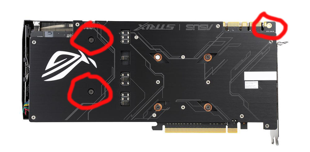
I’m not sure if the screws were M2 or M2.5 (M2 is more probable here, so try that first), but it was one of the two. Get yourself two from each and try. Their length should be 10mm (plastic) + 10mm (spacers) + 4-5mm (GPU body), so try to buy 25mm first and see if that’s sufficient. First thing you’ll do is that you will take the two screws out of the GPU. Store them somewhere safe, where you can find them. Next, you will have repeat the process that you did with the CPU radiator:
- turn the GPU around
- put acrylic on it
- mark the two holes
- drill holes into acrylic (M2 = 2mm bit / M2.5 = 2.5mm bit)
- widen the holes on the top (1-2mm)
Try to be as precise with marking the holes as you were when you marked the CPU radiator holes. You will need spacers here as well – we used the same ones that we used with CPU radiator. The problem is that because the screws are so small, the spacers are kind of loose. You can again use washers to reduce the space to minimum so the GPU fits, if you do this, the spacers will get squashed by washers and won’t tremble/move around.
In addition to the two screws, you will have to mark additional spot – right top on the picture. This time the screw will be put in from the top (I told you that GPU mounting is a tiny complex, right?), so you have to mark the space on the top side of the acrylic. My suggestion is – try to mount the two bottom screws, turn the GPU+acrylic around and mark the third one. You will use a M2 screw for this hole. And here’s where it gets tricky.
This screw is the only one that holds the GPU on the left side (top view). It has to be sturdy, so it should go as deep as possible. 10mm (acryl) + 10mm (spacers) + 3-4mm (GPU body + washer) = 23-24mm. Try to buy one like this – if you cant, get one in 20mm length and you will sacrifice some mms in acrylic. At the end of the day, I think we did the same thing, and we can’t complain about the result at all.
Now, put the main board mounting screws through the plastic and then screw the small GPU screws from the bottom in the GPU. Place something between the GPU and the acrylic to even out the difference, otherwise you will break the screws when you turn it back around. Turn the GPU top side up and screw in the M2.5 screw together with a washer and a spacer. Then, secure the mounting screw from the bottom side of the main board with a hex nut.
If you made it this far, then big congratulations to you, because you’re almost done with the whole rig and the hardest parts are behind you!
Plug in all cables and test
I think this phase was the most exciting moment of the first half of year 2018. I hope it will be the same for all of you, I know you worked hard and deserve some good result; been there. 🙂
For now, don’t put your cables through the cable holes – leave them on top of the rig in case you have to change the configuration.
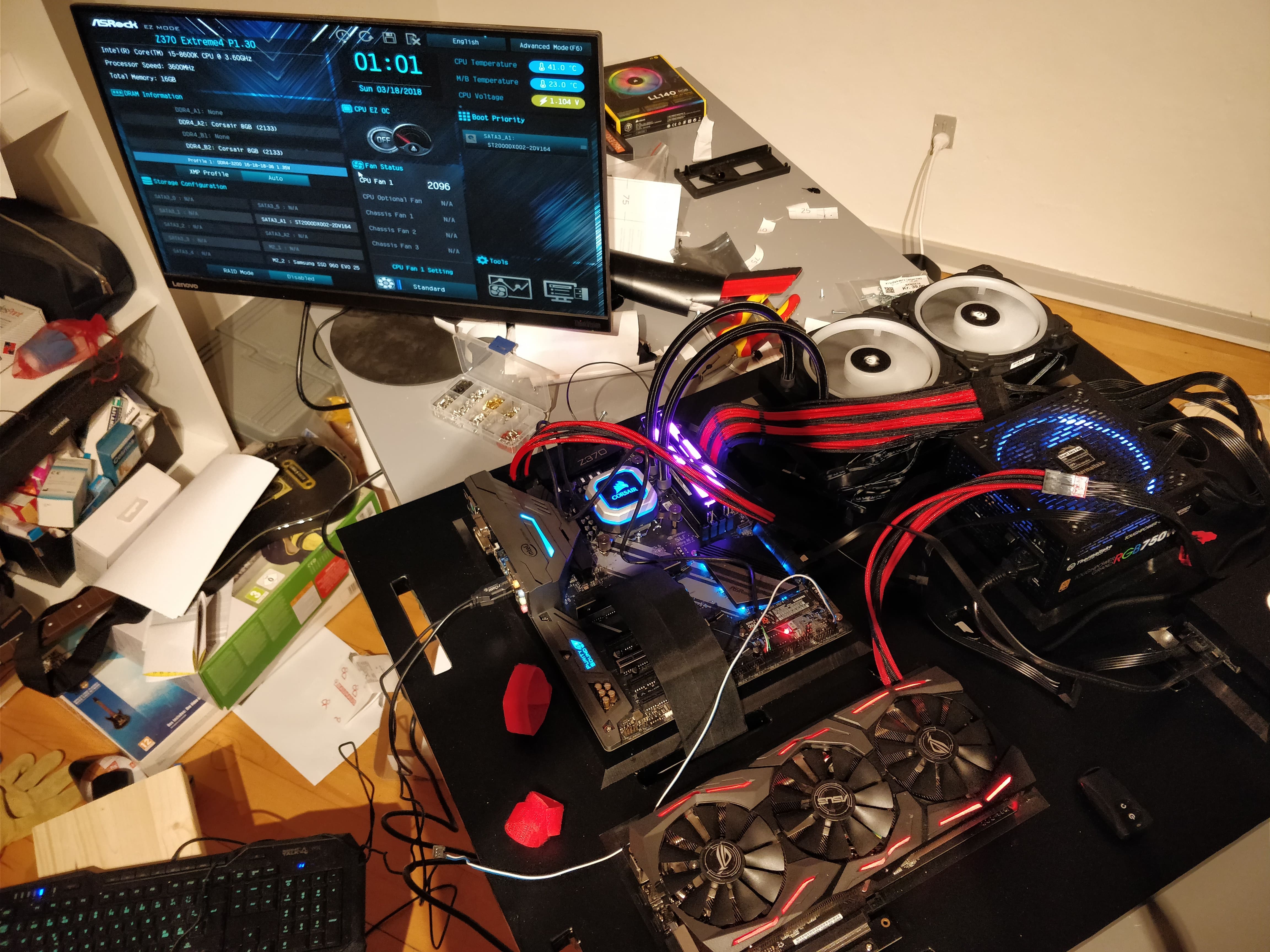
Plug in all the cables – and I mean all of them. Lightning components, GPU riser, Thermaltake Ttmod cables… everything. Then, plug your computer PSU into electricity, the motherboard should light up. If it did, I’m really f****n happy for you, because is the first thing that suggests that everything is fine.
Connect a monitor or a TV and turn on the computer. Go to the BIOS and check if every device was recognized (especially hard drives) and if the temperatures aren’t suspicious. Then, install Windows on it. While this is going on, check the temperatures with you hand – this is the first time your computer is on and the next few hours won’t be so fun. Install some benchmark software, such as PCMark, and some free games, like Dota 2 or so. And test… test… and test even more.
If everything works as intended, you can turn it off, plug out the power source and move all cables under the computer – this is what your cable holes were here for the whole time. You don’t have to do any cable management just yet, that will be the last step of the building process.
Wood triangles (wall spacers)
Because all the cables behind the computer together have some volume, we need to make some standoff which will allow space for these cables. You obviously do not want to have the computer too far away from the wall. For our rig, we used plywood of the same height as the main board, which was 25mm. You can see this in chapter Get the plywood.
If you got the 2 pieces of plywood as I told you, your task is to cut them to two pieces so you’re left with two triangles. These don’t need to be masterpieces as they won’t be visible from outside that much. Then, cover them with the adhesive foil that you used for main board as well.
Now is the time to make holes into the wood. For this, you will have to select screws in advance, so you know what drilling bit you will use. These screws will be there to hold the main board and wall spacers together and prevent standoffs from moving around, so you need screws that are 50mm long (main board = 25mm, wall spacers = 25mm), and you have two options here:
- Either you buy a screw and secure it with hex nuts from the bottom side (you will also need to widen the screw holes from the bottom of the wall spacers to let hex nuts in, so they don’t stand in the way between the rig and the wall)
- Or you buy a regular screw without hex nuts and just drive it in without fixing it
The second option is easier and it also does not matter that much if you fix it using hex nuts, because these wall standoffs will be squished between the wall and the main board.
On our computer, we used 50x6mm screws – if you do the same, use 6mm drilling bit for holes. When the holes are done, you can mount the standoffs. I’m sorry about the picture, I didn’t take one of them standoffs, but below you can see what you should end up with. Leave space in the middle of the 2 screws for one big one that will go through the wall.
- Links:
-
Our adhesive foil – https://www.bauhaus.dk/d-c-fix-klaebefolie-uni-lack-sort-210×90-cm.html
Position the rest of the LED strips
I’m pretty sure you noticed that you still have 3 LED strips left. It is completely up to you where you place these – we put them 5mm away from the top, left and right side of the main board (from backside) to add a nice backlight. You can do the same, or place then else – your decision. Be aware though, that if you put them too close to the middle of the backside of the main board, the backlight will be too little to see.
Place temperature meters on their place
The good thing about these four meters is that you can place them wherever you want. They can help you a lot at the beginning of using the computer. Testing will require watching temperatures as well and these four – if placed under components – can help you track if the airflow under components is sufficient (remember all the spacers?). We already placed one under the motherboard, because it is important to watch this place for any CPU overheating. You can place the rest three where you want – just tape them, or glue them on the desired place.
Think about putting one to the backside of the main board. Just as any computer component, Commander Pro, Lightning Node Pro, RGB Fan Led Hub, LED strips, or some cables can produce heat, so this could help you reveal a problem which could not be identified otherwise.
Fasten all screws
We’re getting close to the end of the building process. Before we mount the computer on the wall, you have to make sure that all screws are holding the load perfectly. Fasten all of them – all wall standoff screws and all hex nuts that hold acrylic and main board together.
Plug extension cables & Move cables behind
It’s time now to plug all extension cables and then move all cables to the backside of the computer. Having extension cables is a great advantage. This computer is built because you want it to look top notch. I hope I do not have to explain to you how awful it would look if you connected your mouse, keyboard, monitors, etc., all fron the front side of the computer. Yes, extension cables are a big slap for your wallet; not getting them though would be a waste of potential.
Required extension cables (length is up to you, we used 3 meters):
| 5x | USB 3.0 | male-female |
| 5x | Audio 3.5mm jack | male-female |
| 3x | HDMI (1xMB, 2xGPU) | male-male |
| 2x | DisplayPort 4K | male-male |
| 1x | Power supply (230V) | — |
| 1x | LAN cable (Cat6/6a) | male-female |
| 1x | Optical Audio | male-female |
Cable management
This is a very pleasant part and be as creative as you like. I will not tell you how, why, where, and so one. The only thing I want to warn you about is that sometimes your cables will cross with another cables. They cannot exceed 25mm in height, otherwise when you put them on the wall, they will get squeezed and might get damaged.
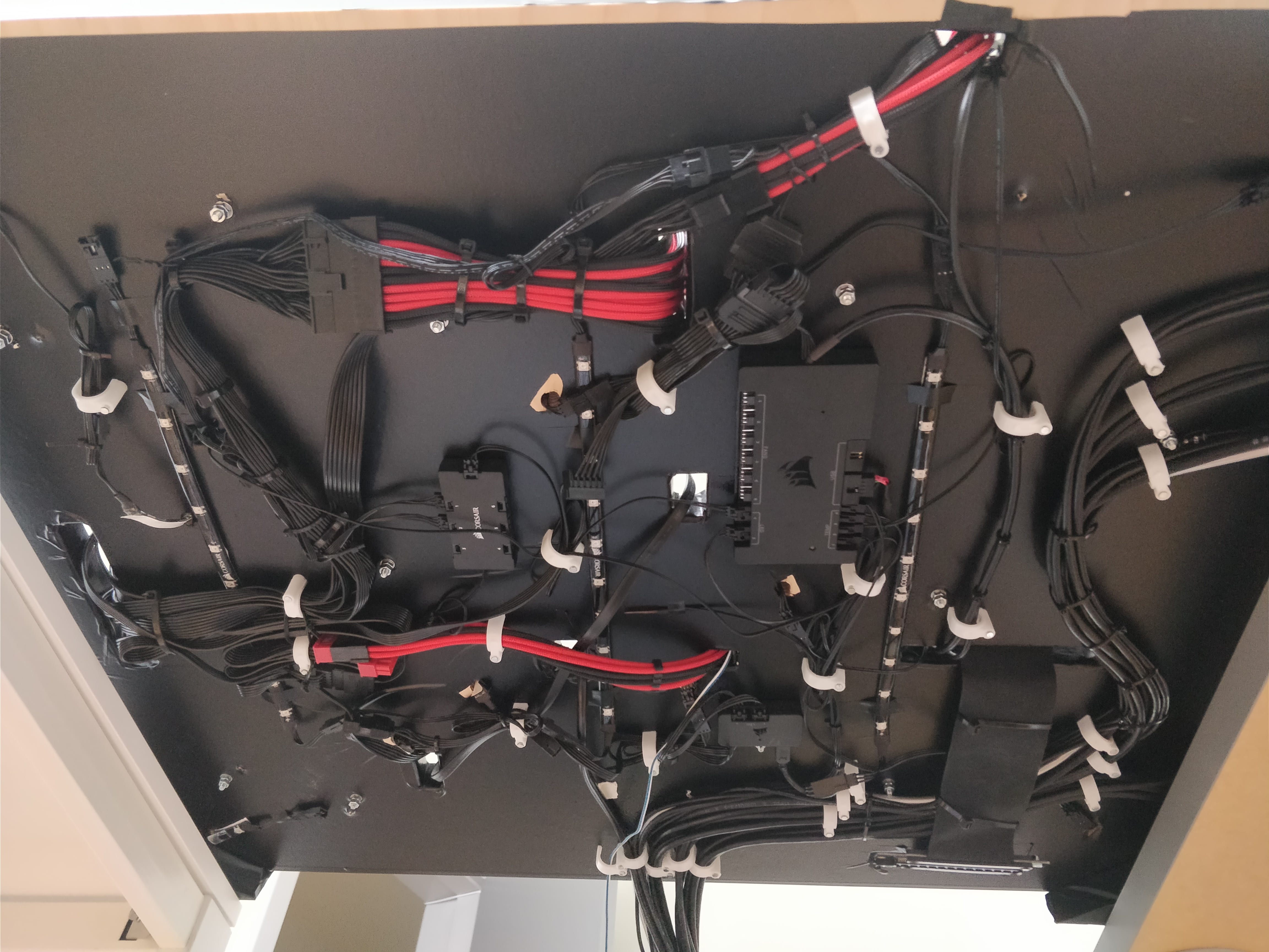
Below you can see how I solved our cable maintenance. I used cable ties to get cables together, and cable holders, which I pinned to the main board.
- Links:
Mount the rig on the wall
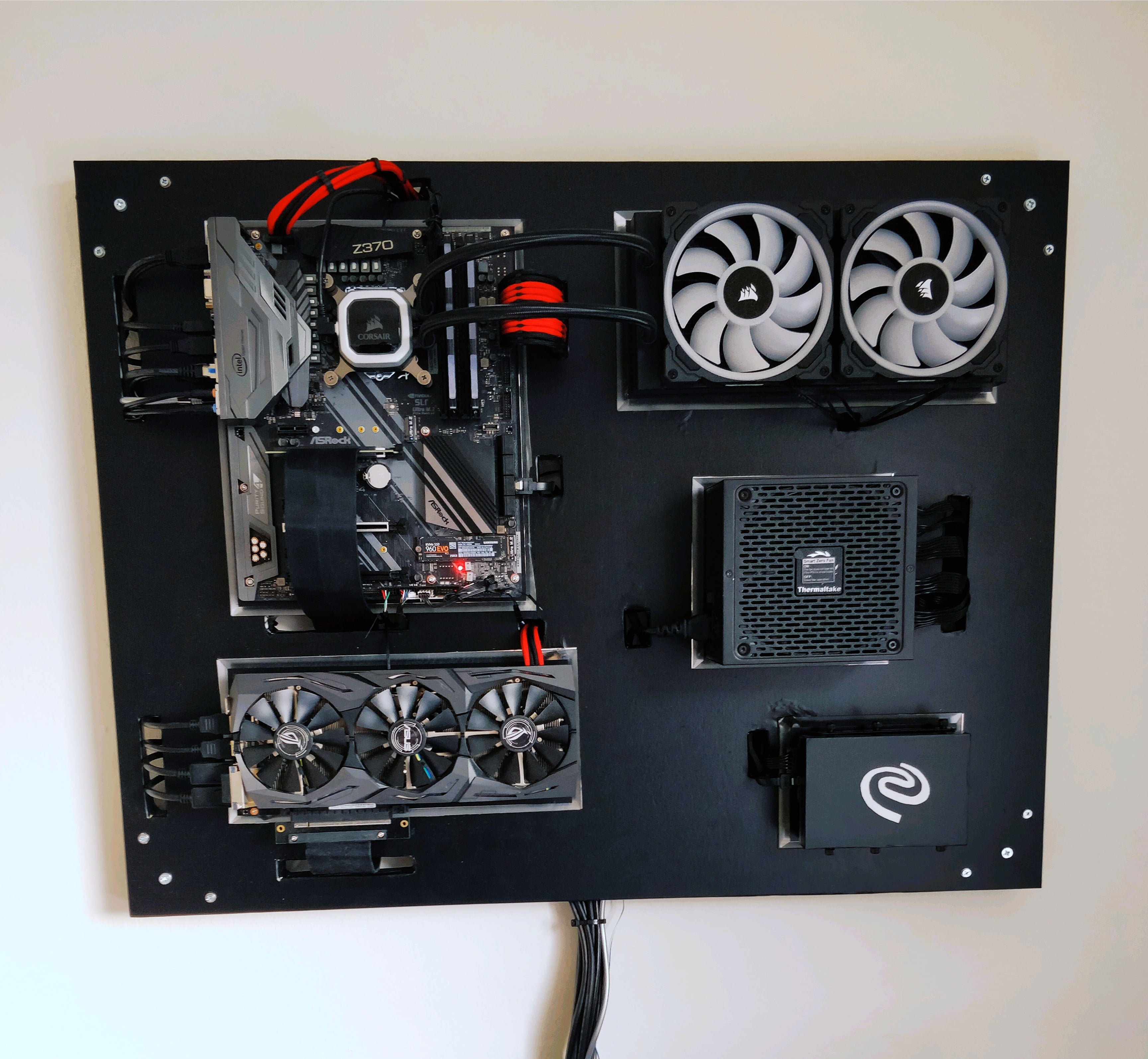
Hooray, the last step! It’s time to hang the PC up!
Find some strong screws which are at least 80-100mm long (the height of the PC is 50mm). Drill four holes in the rig – one for each corner, in the middle of the two wall standoff screws. Then, drill holes in your wall, with the same drilling bit size.
By now, the rig weights more than 15kg, so ask some strong friend to hold it up while you screw the screws in. After you’re done, check if the rig holds perfectly on the wall.
And this is it! Congratulations, you have successfully built your wall computer! If you got this far, you must be a very persistent fella… but it did pay off, didn’t it? 🙂 There are hours and hours of testing ahead of you. I wish you luck and fun with your new rig. 🙂
- Links:
-
Screws 100x10mm – https://www.bauhaus.dk/dybel-med-skrue-100×10-mm-4-stk-stabilit.html
Final words
If you like this tutorial, please help by sharing everywhere you can.
[…] Image Source […]
[…] How to Build a Wall-Mounted Computer – Part 2: Step by Step Guide […]