How to Build a Wall-Mounted Computer – Part 2: Step by Step Guide
At the beginning of 2018 me and my friend finished building this wall computer. We’ve been testing it ever since – one month of stress-testing, followed by a regular use of the computer (programming, games and regular tasks). Because everything works flawlessly, I decided to write this documentation to make it easier for all of you to build one of these for yourself. There is multiple advantages of having this bad boy that we noticed over the time we had it at home:
- It looks amazing and every single component is visible
- You save space on the floor
- No more overheating
- You no longer have to dust/dirt off your components every month
- You’re the master of your cables. There is just one chunk of cables coming out of it and it’s up to you if you build it into the bricks, cover it with plastic tray, or whatever you want to do.
- There are hundreds of lighting combinations, it really looks sick as hell


Project duration
We only had time to build it about twice a week for a few hours, plus I was working on it alone for additional two weeks almost every day, also a few hours a day. Because delivery time of the components and other materials takes a lot of time, I expect that when fully committing to this project, it could take roughly one month to build.
Placement of components
It is, of course, completely up to you how and where you place the components. I made the specific design with respect to overheating prevention.
Let’s take the motherboard as an example. No matter what you do, the MB will always emit heat from the back side. Heat, naturally, rises up, so if you place your GPU right above the MB, it is very possible that the GPU’s temperature will be higher than it would be if you placed it somewhere else.
This is an example of a fact that you should think of when you do your own design. That’s not all though.
The way we attached PSU to the wood base is that we disassembled it and used the four screw holes to secure it. This was one of the biggest headaches during this projects – PSUs do not have as many screw holes as you might think they have. We chose the most esthetically pleasant solution, although we broke the warranty of the component.
You have to be extra careful with your design, everything is possible, but it has its drawbacks.
Selection of components
We were putting this rig together in March and April 2018 and I spent a riddiculous amount of time on the internet watching reviews and comparisons to choose the right components. It was also super important to have RGB lights/static colors on almost all of them so the rig has the best possible outlook. It’s not likely that you will use the same components – they are probably outdated already (as of 2019… technology, right?). Feel free to use any that you want, but keep in mind that you will need specific screws for your GPU, PSU and possibly water cooler radiator.
You will have to look for screws according to your rig. I will try to give you some idea what the screws could be, but you have to experiment. Screws are not expensive so it will not cost you a lot to try more kinds of them.
For our build, the following components were chosen:
| CPU | Intel Core i5-8600K 3.6GHz |
| CPU Cooler | Corsair Hydro H115i Pro RGB Water Cooling |
| CPU Cooler fans | 2x Corsair LL140 Dual Light Loop LED RGB |
| GPU | ASUS ROG STRIX 1070 8G GDDR5 Gaming |
| GPU Raiser | 2x Li-Heat PCIe Gen 3.0 Ribbon Riser Cable v2 (45cm + 15cm) |
| MB | ASRock Z370 Extreme4 ATX Socket 1151 |
| RAM | Corsair Vengeance RGB 16GB DDR4 3200MHz |
| SSD | M.2 2280 Samsung 960 EVO 250GB PCIe 3.0 x4 (NVMe) |
| SSHD | Seagate Firecuda 2TB SSHD 6GB/S SATA 64MB + 8GB NAND |
| PSU | Thermaltake Toughpower Grand RGB 750W |
| PSU cable mod | Thermaltake TtMod Sleeve Cables Black/Red |
Lightning & Colors
Each components is placed on a piece of acrylic which has a strip under it (five strips in total). The rest of the strips are placed on left, top and right backside of the board to give the computer a nice backlight. The bottom one was eliminated because of the cable placement on the backside, but with a bit of tweaking, or different cable positioning, you can have lights on all four sides. Each of the strip is individually controlled, which means that there are thousands of color combinations that you can make.
There is also an easier solution (and cheaper, too). Our ASRock motherboard has an RGB connector on it. You can take one very long LED strip and drag it through every LED hole on the wood board and to any place behind it. Or you can cut it to pieces and solder it for better looking solution. Be careful though! These connectors usually have a limitation to how many LEDs they can power, which means you can get a 500 LED strip, but only 10% of them will shine.
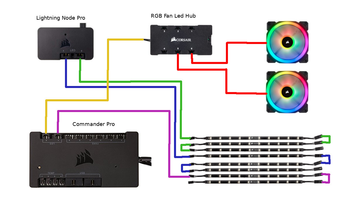
There are 5 light strips under components, 3 strips on backside and 2 fans on the cooler’s radiator that we want to control. To get as big compatibility as possible, I chose to get all lightning components from Corsair (notice that RAMs are Corsair too). It was also because it seems that Corsair offers the biggest variety of components for a reasonable price.
Commander Pro is the main node in the lightning setup. Because it cannot power all the 8 LED strips (it’s limited to 3 on each connector, 2 connectors in total), we needed aditional node for this – Lightning Node Pro, which powers 6 LED strips. We also have two fans on the radiator, each having it’s own LED cable. We connect the rest 2 LED strips in series to one of the 2 available slots on Commander Pro. Because we have only one LED slot left, but 2 fans need to be connected, we get a third node – RGB Fan Led Hub, which has 6 slots for fans – plenty of space for our two fans. Then, we connect the Hub to the one Commander Pro LED connector that is free.
| Main node | 1x Corsair Commander Pro |
| LED strips node | 1x Corsair Lighting Node Pro |
| FAN LED node | 1x RGB Fan Led Hub |
| LED strips | 8x Corsair Lighting Node RGB Strip |
With all pieces of the puzzle in the right place, here is the complete list of lights that can be controlled on the whole computer:
- 5x Light strip under acrylic (one for each component)
- 3x Backlight strip (left, top and right)
- 2x Fans on the CPU cooler radiator
- 3x Motherboard LED colors (sound card, outputs and chipset cover)
- 2x RAM light
- 1x CPU cooling unit color
- 2x GPU lights colors
- 1x PSU led-ring color
Price tag
The final price depends on what components you buy. It also highly depends on your hardware tools situation. If you are already equipped with tools like drilling machine, jigsaw and so one, your wallet will stay a bit thicker than if you had to buy all of them. In our case, we only owned basic tools, like a bunch of screwdrivers, a hammer etc. As we live in Denmark and prices might be a bit higher here than somewhere else in the world, we also spent a little more. Also, as this was the first time we built anything like this, we had some additional expenses for extra screws, wooden board and LED strips. We bought most of the hardware, tools and equipment in local shops, which affected the price too – if you have time to wait, order stuff from ebay/amazon, it can save you a lot of money.
All in all, we spent roughly 21.000 DKK / 3000 EUR.
Temperatures
Ever since we started to build this computer, we knew that putting components out in the air will help temperatures a lot. Each of the five components are placed on a piece of acrylic, separated by spacers from 8mm to 25mm (component by component) to allow air flow. During the one-month testing, the CPU temperature has never gone higher than 45°C / 113°F. The GPU temperature was at maximum of 58°C / 136°F while playing CSGO 1080p on maxed out settings with 250-320 FPS. World of Warcraft (April 2018 update) was at 60-65 FPS on maxed out settings while in fight in a 25 raid. None of the components were overclocked, but these low temperatures allow you to go way higher when it comes to performance.
There are 4 temperature sensors powered by Commander Pro. You can place them in any place you want. This gives you a better overview of the temperature in the whole system. We have ours between the motherboard, GPU and radiator and the acrylics under them to measure if the air ventilation is good enough. The last one is attached to the backside of the computer, to also make sure there is no monkey business going on there, too.
Testing & Gaming
The testing setup consisted of two 1080p monitors, primary was running the game in full screen windowed mode (borderless), while secondary was playing a video from Youtube in Google Chrome while having 19 more tabs opened and having 10 more applications (including RGB controller apps) running in background. One of these applications was Steam’s Wallpaper Engine running a video on both screens on 25 FPS (allowed to run in background). We tested following games in this environment:
- World of Warcraft (latest patch to date 14-04-2018), maxed out settings on 1080p, in fight in 25-man raid: 60-65 FPS
- Counter-Strike Global Offensive, maxed out settings on 1080p on public Dust II server: 250-320 FPS
- Dota2, patch 7.14b, maxed out settings on 1080p in late-game 5v5 fight: 180-220 FPS
- Rocket League (latest patch to date 07-05-2018), maxed out settings on 1080p in 4v4 Chaos game (Aquadome stadium): 105-140 FPS
As we did some stress testing, we also had to test endurance. We had it started for 48 straight hours: 6 hours heavy gaming-> 2 hours video rendering -> 10 hours rest (only background tasks) -> 6 hours heavy gaming -> 10 hours rest (only background tasks) -> 2 hours video rendering -> 10 hours rest (only background tasks) -> 2 hours heavy gaming
The temperatures were persistent and we did not notice any drop in FPS performance. We also did something that we call a confusion test. Until this day, there is a Windows 10 installed on the machine together with three revisions of Ubuntu 16.04. We restarted the computer more than 25 times in less than 15 minutes and each run was made on a different operating system. Measuring the startup time also showed persistent results, which meant that both the NVMe SSD and the secondary SSHD work perfectly.
The power output that this bad boy drew was never higher than 450W, meaning that there is plenty of space for overclocking.
Output cables
To make your life easier and also to make the cable management as nice as possible, we connected an extension cable to most of the output slots. You can plug your devices to the endpoints of extensions cables coming out of the computer. It is possible to connect following cables without any need to plug them directly to the front side of the computer:
- 5x USB 3.0 (extension cable)
- 5x Standard Audio 3.5mm Jack (extension cable)
- 1x Optical Digital Cable (extension cable)
- 1x LAN Cat 6a S/FTP (extension cable)
- 1x 230V Power supply cable
- 2x HDMI 2.0 cable (coming out of graphics card)
- 1x HDMI 2.0 cable (coming out of motherboard)
- 2x DisplayPort 4K cable (coming out of graphics card)
- 1x Power button
Length of the cables coming out from the computer ranges from 2m to 2.5m, which should be enough to allow a lot of flexibility for your desired placing of computer and monitors. You decide if these extension cables are required for you. I have seen a few wall builds and some of them had the cables connected directly to the front side of the rig. To be honest with you, you’re already spending big money for it, just get the cables, otherwise it won’t look nearly as good.
Perks & Tweaks
There is literally no limits to what you can do. In the initial phase (before it came to spending money of course), I planned to mount a pilot on/off switch on it, just to make it especially cool.
We also planned to mount Amazon Echo Dot on the computer. The plan was to have Alexa start the computer on and turn it off by voice, use voice commands to perform actions in Windows and – nevertheless – use Alexa for all other things that are native to it.
One thing that we managed to bring to life was a remote controller for startup, shutdown and reset of the computer. We bought a thing called Silverstone ES02-USB which is plugged into one of the USB sockets on the motherboard and comes with a small remote controller (see pictures above). Now there is two ways how to turn on the computer. There is a classic push-to-start button that is a part of the chunk of the cables coming out of the computer. You can place it anywhere you want, and style it in any way you desire, the possibilities are unlimited and it’s all up to you
And then there is the remote switch controller that allows you to start or restart the computer from up to 5 meters away. This is what you will use most of the time, if not always – we found it extremely cool to use so far.
These are only a few suggestions – I’ll leave the rest to your creativity.
What to be aware of
If you decide to go with a water cooler, you have to account a risk of water leak. Although, it’s not probable to happen, especially if you don’t plan to move the computer around. Ours was put on the wall and was never touched; it’s been 10 months and nothing seems to be wrong. I also do not expect anything to go to crap, because I’m not even touching the cooler pipes, or anything close to the whole AIO. But, there is always a risk… If you can’t take it, redo the design and go for air cooling instead.
What’s more probably to happen is one of the following situations:
- you want to swap a component
- lightning nodes break
- cables on the backside loosen from their ports
- some of the LED strips stops to work
- and so one …
You are forced to take the computer off the wall. In the better case, you simply replace what you desire. The worst case scenario is when a LED strip stops to work. Replacing is a matter of 30 minutes. But – I can’t stress this enough – acrylic is a sticky bastard. You have to be extremely careful when screwing into or out of acrylic and I warn you not to use automatic screwdriver. If you do the screwing too fast, you will melt the acrylic inside the hole and you either break the screw, or wont be able to take it out.
I always was and I always will be saying that a wall computer is for the more technically skilled people. If you can’t handle the risk of having to disassemble it over time, don’t get one.
It is hard to mount the PSU in a way where it holds sturdy and looks good. Some people mount them by using a mounting bracket on the side of the main board and then mouting the PSU as you do in a standard PC case, using the screws on PSU’s side. The result does not look good at all and it is also hard to find a bracket that would fit (you can also make one yourself or cut it off some old PC case, but still…). What we did is that we disassemble the PSU we have and use the 4 screw holes on the bottom to mount it on the acrylic. This involves removing old screws and replacing them with the same width, but bigger height; but most importantly, it involves removing the warranty. I don’t know how comfortable you are with that, but this is how we do it in the tutorial – you are welcome to do it your way, but you have to find a solution.
I will try to provide links to material, such as screws or foils that we used while building our computer, but these sites will be mostly Danish as we live in Denmark now. You can easily find some other sites with other products and if you don’t speak Danish, just use Google Translate to get an understanding of what the specific Danish website says.
I will not explain every small thing, unfortunately. You will have to figure some things yourself. For example, when you’re mounting the HDD bracket onto the acrylic, I assume that you will mount it in a way where (after mounting HDD on the bracket) the connectors will be facing the cable hole. Logical things like this will not always be explained in this tutorial. Please, think every step through before you start working.
If you think you’re ready, follow the second part of this series – the actual building process.
How to Build a Wall-Mounted Computer – Part 2: Step by Step Guide
[…] How to Build a Wall-Mounted Computer – Part 1: Overview […]